03. Camera Technology Overview
Camera Technology Overview
ND313 C03 L01 A06 C14 Intro
In this section you will learn about the basic properties of a camera. We will start from the most basic model called a „pinhole camera“ and then progress to using lenses, which are a key component of camera systems. You need this knowledge in order to understand how a camera creates images, which of its properties influence image appearance and quality and which parameters you have to consider in order to successfully extract meaningful information from these images.
The Pinhole camera
A very simple camera can be designed by placing a light barrier with a tiny opening (the pinhole) between an object of interest. The light emitted by the object passes through the pinhole and lands on a photosensitive surface which stores the light information as an image. The reason why the pinhole has been made so small is to avoid image blurring due to superimposing rays of light stemming from various parts of the object of interest.
This simple principle has been well known for centuries and was for example used by artists to create photorealistic portraits.
A formal model of the pinhole camera model is shown below.
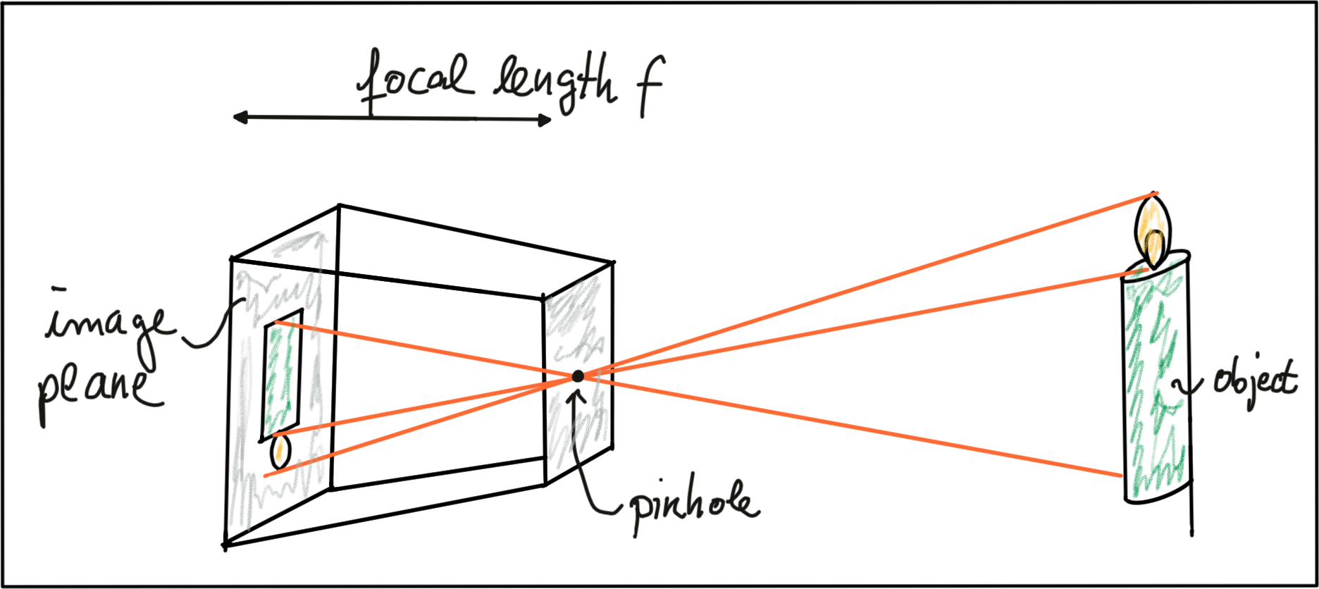
The photosensitive surface on the left is called the image plane whereas the pinhole is called the camera center . The distance between the camera center and the image plane is called the focal length f .
A point P on the object of interest can be mapped to a point P’ on the image plane by casting a beam through the center of projection until it hits the image plane as shown in the figure below.
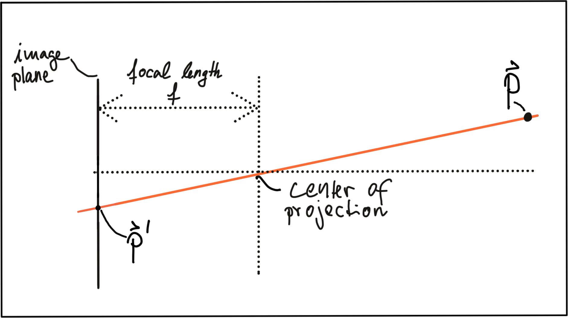
In three-dimensional space, the relation between P and P' is expressed by the following equations:

Based on these equations, we are able to compute the 2D position of an object on the image plane, given the 3D position of the object in space as well as the focal length of the camera. Note however that the resulting coordinates x’ and y’ are metrical coordinates and not pixel positions yet.
The problem with pinhole cameras is that the amount of light passing through the pinhole is not sufficient to generate a decent image on an image sensor. If one were to increase the amount of light by widening the pinhole opening as shown in the figure below, rays of light from other parts of the object of interest would superimpose each other, leading to a blurring effect: The larger the pinhole, the brighter the image but at the same time, the more severe the blurring of the object on the image plane would be.
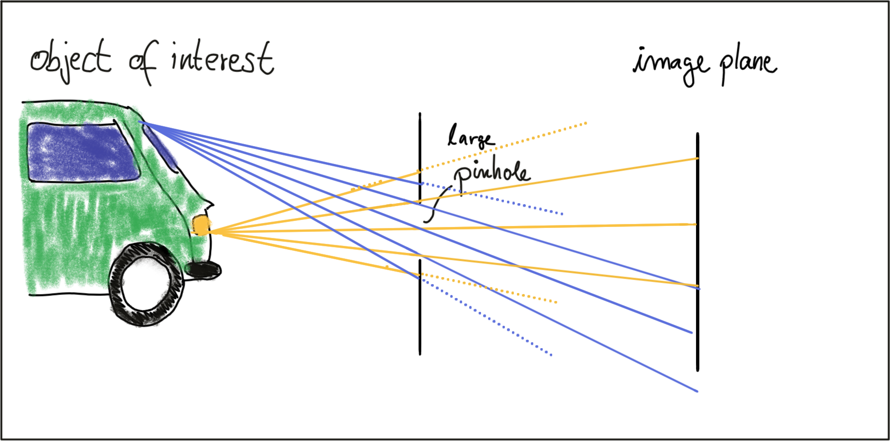
One way to solve this problem is use a lens, which is able to capture multiple rays of light that emanate from the same point on the object of interest. So let’s look at lenses next.
Lenses and Aperture
A properly sized and positioned lens refracts all rays of light that emanate from a point P1 on an object in space such that they converge to a single point p_1' in the image plane. Rays of light passing through the lens center are not refracted however, they continue on as a straight line until they intersect the image plane.
Points on the object that are closer or farther away, such as P_2 , appear out of focus on the image plane, because the set of light rays emanating from them does not converge in a point but rather in a circle with a finite radius instead. This blurry circle is usually referred to as circle of confusion (COF) . To reduce blurring, an aperture can be used, which is a concentric opening of usually adjustable size placed directly behind the lens. The following figure illustrates the principle:
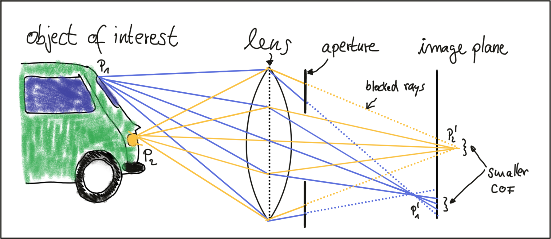
By reducing the diameter of the aperture, light rays passing through the lens on the outer edges are blocked, which reduces the size of the COF on the image plane. It can easily be seen that a smaller aperture results in reduced blurring, but at the expense of low light sensitivity. The larger the aperture, the more light rays are focussed onto the image area, resulting in brighter images with a better signal-to-noise ratio.
So how can we compute where an object in space will appear in the image? Given a 3D point in space, its 2D position on the image plane after passing through a lens can be computed similar to the pinhole camera. In practice, lenses introduce distortion into images, depending on the lens type. The distortion most relevant to practice is called “radial distortion”. It is caused by the focal length of the lens not being uniform over its diameter. Therefore, the magnification effect of the lens changes depending on the distance between the camera center (the optical axis) and the ray of light passing through the lens. If the magnification increases the resulting distortion effect is called ‚pin cushion distortion‘. It it decreases, it is called ‚barrel distortion‘ instead. Barrel distortions usually occur, when wide-angle lenses are used. In the figure below, both distortion types are illustrated.

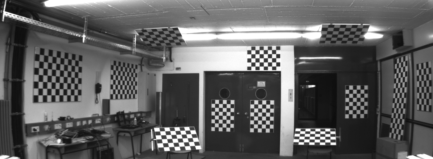
When extracting information from camera images, many applications seek to draw conclusions on the spatial location of objects of interest (e.g. vehicles). To get there, the distortion effect of the lens must be removed or at least mitigated. The relevant process is called calibration. For each camera-lens-setup, a calibration procedure must be performed so the distortion parameters can be individually computed. This is usually done by taking a set of pictures of well-known objects such as planar checkerboard patterns, from whose known geometry all lens and image sensor parameters can be robustly derived. The process of removing distortions from a camera image is called rectification . In the image below, the calibration setup used to rectify most of the images in this course is shown. It can easily be seen that lines at both left and right are distorted significantly.
It is beyond the scope of this course however to go into the details of distortion correction. Most of the images you will be using are already free of lens distortion. When using your own camera setup however, a calibration procedure must be performed when precise measurements and a spatial reconstruction of objects is the goal.
As mentioned before, the projection of points in 3D space onto the image plane does not directly correspond to what we see in actual digital images, which are made up of thousands of picture elements or pixels . To understand how images can be expressed in discrete pixels, we need to take a closer look at the above-mentioned camera model once more. In the figure below, the camera center is shown with a position O in space along with its own coordinate system with axes i , j and k , where k is pointing into the direction of the image plane. The position C' where k intersects the image plane is called the principal point and represents the center of the image coordinate system.
The first step after projecting a point P in space onto the image plane is thus to subtract the principal point coordinates so that the discrete image has its own coordinate system centered in e.g. the lower left corner of the image plane

The second step in the transformation process is to move from metric to pixel coordinates. To do so, we can use parameters k and l provided by the calibration procedure which convert meters to pixels and which can be easily integrated into the projection equations as seen below. Note that in image coordinates, the y-axis has its origin in the upper-left corner and is pointing downwards.
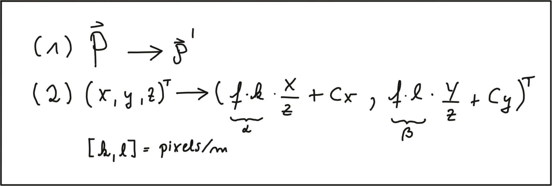
In a later section of this course, we will be mapping Lidar 3D points into the camera image. To do so, we will make use of these equations. Specifically, the product of focal width f and k and l respectively (also termed alpha and beta) will be used in a calibration matrix to simplify the mapping operation significantly.
One final note on image rectification: In many applications (e.g. feature tracking) it makes sense to process the original image to avoid interpolation errors when the rectified image is computed and transformed pixels do not fall exactly onto the center of a discrete pixel in the rectified image but close to the border to another pixel instead. In such a case, it is advisable to locate the features in the unmodified original image and then transform the resulting coordinates using the equations above. When using deep learning based on a set of trained weights, it makes sense to rectify the image first before feeding it to a network - if we would use the original image, distortions (such as from a fish-eye lens) would lead to detection errors as networks are usually trained on a distortion-free image set.
ND313 C03 L01 A07 C14 Mid
Imagers and Bayer Pattern
In this last section, you will learn how rays of light with a certain wavelength are converted into color pixels that can be stored digitally.
When an image is captured by a camera, light passes through the lens and falls on the image sensor. This sensor consists of light sensitive elements that register the amount of light that falls on them and convert it into a corresponding number of electrons. The more light, the more electrons are generated. Once the exposure time is complete, the generated electrons are converted into a voltage, which is finally transformed into a discrete number by means of an A/D-converter.
Currently, there are two main image technologies, which are CCD (Charge-Coupled Device) and CMOS (Complementary Metal-oxide Semiconductor). Both technologies convert electrons into voltage and are inherently color blind, as they can not distinguish the different wavelengths which generate the electrons. To enable color vision, tiny filter elements (also micro-lenses) are placed in front of each pixel which only allow a certain wavelength to pass through. One common way to map wavelength to color is to arrange the filter elements in an RGB (Red, Green, Blue) pattern to allow the primary colors to pass through individually, which gives us three individual images - one for each primary color.

Mixed in different combinations, RGB values can produce most of the colors visible to the human eye. When each discrete color value is coded with 8bits (i.e. 256 values), a total of 16.7 million different colors can be created with the RGB filter concept. The most common way of arranging the RGB filters is called a Bayer pattern , which has alternating rows of red-green and green-blue filters. Since the human eye is more sensitive to green than to red or blue, the Bayer array has twice as many green color filters. When processing color images in a computer vision application, all three RGB layers are available and it has to be decided which color layers to use. If processing power is limited, the different channels are combined into a gray scale image. In the upcoming section on computer vision, you will be introduced to the OpenCV computer vision library. You can take a look at the conversion formula to get from RGB to grayscale which is used in the method cvtColor here : https://docs.opencv.org/3.1.0/de/d25/imgproc_color_conversions.html
CCD vs. CMOS
In a CCD sensor , the electrons collected in each picture element are transferred from the chip through a single or only a few output nodes. The charges are then converted to voltage levels, buffered, and sent out as an analog signal. This signal is then amplified and converted to discrete numbers using an A/D-converter outside the sensor. Originally, CCD technology has had several advantages compared to CMOS, such as higher light sensitivity and less noise. In recent years, however, these differences have all but disappeared. The major disadvantages of CCD are a higher production price and a higher power consumption (up to 100x more than CMOS) , which usually leads to heat issues in the camera.
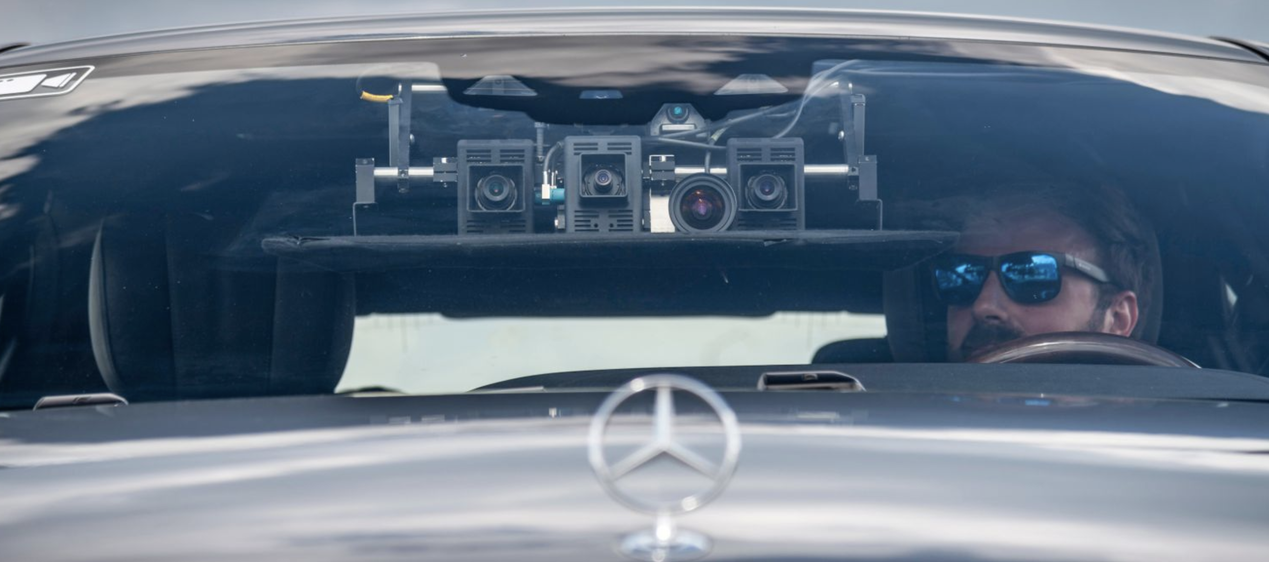
CMOS sensors were originally used for machine vision applications, but the image quality was poor due to their inferior light sensitivity. With modern CMOS sensors however, both quality and light sensitivity have significantly increased. The CMOS technology has several advantages: Unlike CCD, CMOS chips incorporate amplifiers and A/D-converters, which brings a huge cost advantage. With CCD, those components are located outside of the chip. CMOS sensors also have a faster data readout, lower power consumption, higher noise immunity, and a smaller system size. In automotive applications, almost all cameras use CMOS sensors because of these advantages. The camera setup used for recording most of the image sequences in this course can be found here : http://www.cvlibs.net/datasets/kitti/setup.php
ND313 Timo Intv 07 What Types Of Lenses Do Sdc Use
Review
Now you should have an understanding of how light that is refracted from an object of interest (e.g. a pedestrian) finds its way onto an image sensor after passing through a lens and is finally converted into a discrete color value, that can be processed by a computer vision algorithm. Let’s test your knowledge in a short quiz and then we move on to the next section, which is about basic operations to manipulate and interpret those pixels.
Focal Length
QUESTION:
What is the focal length of a camera?
SOLUTION:
NOTE: The solutions are expressed in RegEx pattern. Udacity uses these patterns to check the given answer
Blurring
QUESTION:
How can blurring of objects in an image be reduced?
SOLUTION:
NOTE: The solutions are expressed in RegEx pattern. Udacity uses these patterns to check the given answer
Principal Point
QUESTION:
What is the principal point and how does it relate to pixel coordinates?
SOLUTION:
NOTE: The solutions are expressed in RegEx pattern. Udacity uses these patterns to check the given answer
Bayer Pattern
QUESTION:
Why does the Bayer pattern put more emphasis on green filters than on red or blue filters?
SOLUTION:
NOTE: The solutions are expressed in RegEx pattern. Udacity uses these patterns to check the given answer